









The problem as it presented itself
The customer arrived with a working prototype and a production problem: the LEDs that passed the bench test were not the ones that survived the line. Nothing in the data was out of spec — the failures were spread across batches rather than concentrated in one lot, which ruled out a supplier problem and pointed at the process instead.
Three measurements separated the causes. First, forward voltage at a fixed low current across a sample of each batch, which showed whether the die set was consistent. Second, case temperature under the real drive condition, which showed whether the thermal path matched the assumption in the design. Third, the reflow profile logged on the line, which showed whether the assembly process stayed inside the qualified window.
The first two came back clean. The profile log showed the peak temperature sitting close enough to the limit that normal line-to-line variation pushed parts past it. This is the most common way a qualified component becomes an unqualified assembly, and it is invisible on the datasheet.
- Measure the process, not just the part. A component that meets its specification can still be assembled outside its qualification.
- Log the profile, do not assume it. Reflow profiles drift as boards and fixtures change.
- Look at failure distribution first. Failures spread across batches point at the process; failures concentrated in one batch point at the supply.
Once the profile was corrected and re-qualified, the field return rate dropped to the level the component datasheet predicts. The component never changed — only the process around it.
An SMT equipment manufacturer required high-power LED strobe lights for AOI (Automated Optical Inspection) systems. The LEDs needed 100,000+ Hz strobe frequency, 50,000+ nits peak brightness, and spectral matching for PCB solder joint inspection (UV 365nm + white + IR 850nm).
Queendom Solution
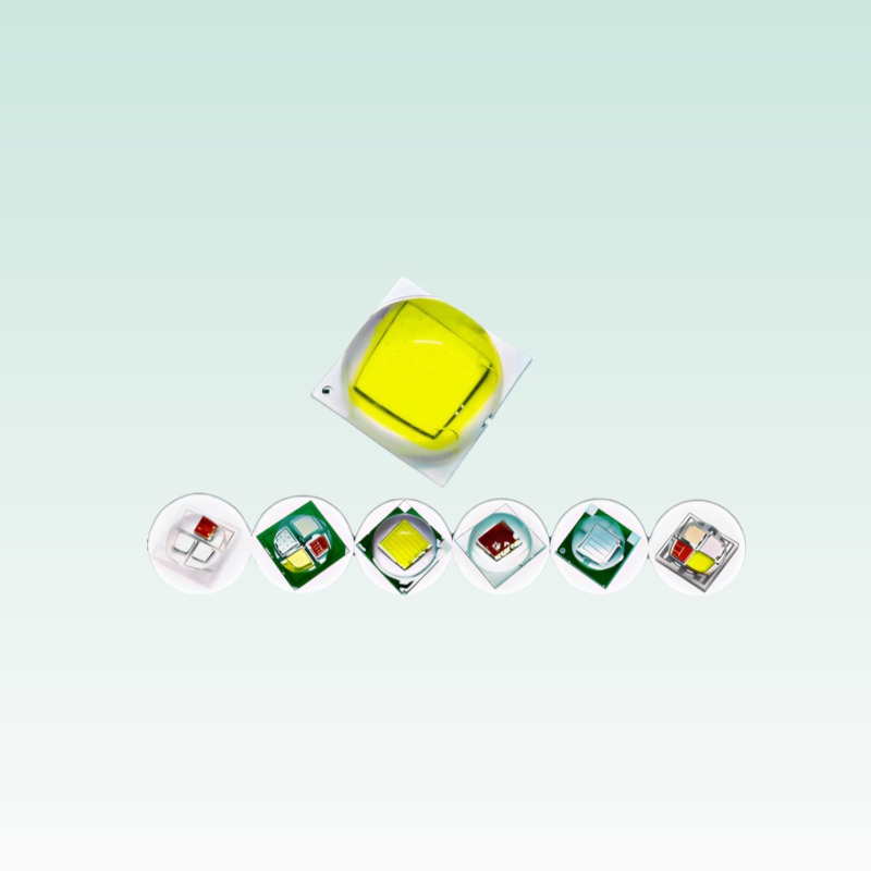
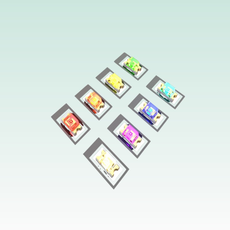
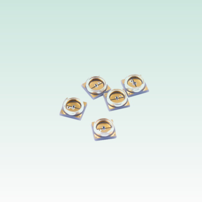
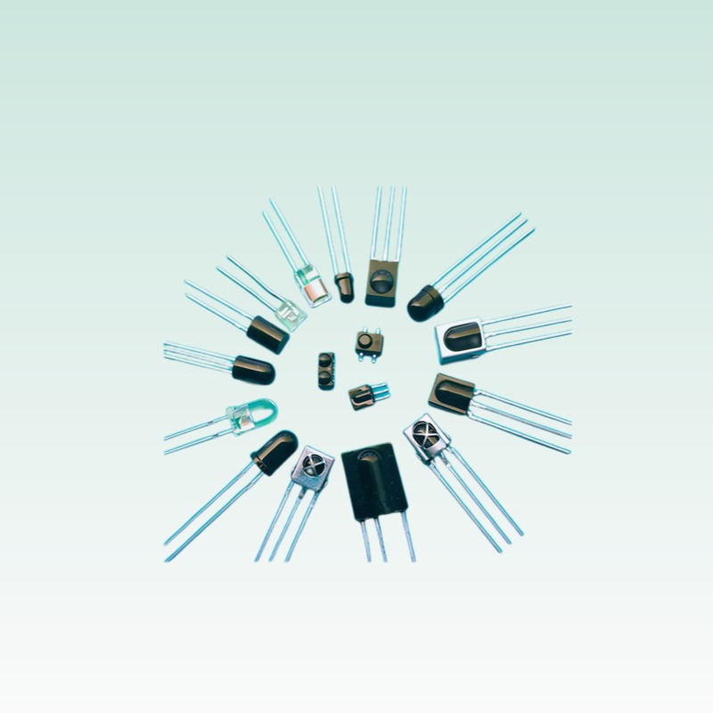
Queendom supplied high-power infrared LED emitters in SMD 2835, 3535, and 5050 packages for AOI (Automated Optical Inspection) machine vision systems. Featuring 850nm and 940nm peak wavelengths with ultra-fast rise/fall times under 100ns, these IR emitters enable high-speed stroboscopic inspection at up to 100 kHz. Optional 365nm UV and white light channels support multi-spectral defect detection for PCB assembly, semiconductor, and precision manufacturing inspection lines.
Key Advantages:
- CSP-0707: Chip-scale package, 0.7×0.7mm
- Strobe: 100,000Hz, 50,000+ nits peak
- Multi-spectrum: UV 365nm + white + IR 850nm
- Line-scan: Dense array for continuous illumination
- Synchronization: <1us trigger-to-light delay
Product Specifications
| Parameter | Specification |
|---|---|
| LED Package | SMD 2835 / 3535 / 5050 IR Emitters |
| Peak Wavelength | 850nm / 940nm IR (with 365nm UV & white light options) |
| Radiant Power | 10 – 80 mW/sr @ 100mA (850nm) |
| Viewing Angle | 30 / 60 / 90 / 120 degrees |
| Strobe Frequency | Up to 100 kHz (pulsed operation) |
| Rise/Fall Time | < 100ns (fast response for high-speed inspection) |
| Operating Temp | -40C to +100C |
| Certifications | CE / RoHS / REACH |
Application Scenarios
PCB Solder Inspection
UV channel for flux residue, white for solder fillet, IR for hidden joints
Screen Panel Inspection
Line-scan illumination, 100kHz strobe for high-speed production
3D Profiling
Multi-angle structured light, IR channel for sub-surface imaging
Case Direction
AOI equipment: CSP-0707 multi-spectrum LED strobe for PCB inspection, 100kHz strobe, UV/white/IR channels.
Related Links
Solution: Machine Vision LEDs Solutions
Product: SMD LED Products
Case Studies: Imaging Principles of LED Optical Systems | Infrared LED Camera Case
Discover how Queendom LED solutions can transform your application.
Contact Us