


SMD LED Failure Analysis & Process Fixes
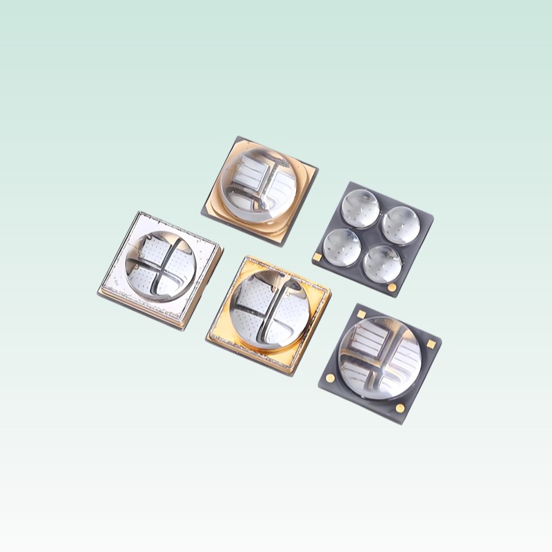
This guide addresses root causes in SMT production and field operation. Focus: 0603, 0805, 1206, 2835, 3528, 5050 packages.
| Symptom | Root Cause | Diagnostic Method | Corrective Action |
|---|---|---|---|
| LED not lighting after reflow | Tombstoning (chip standing up), solder voiding, open circuit | AOI inspection; X-ray for voids; continuity test with multimeter | Optimize stencil aperture ratio (≥0.66); adjust reflow peak to 240–250°C; reduce pad asymmetry |
| Intermittent flicker or dim output | Micro-crack in chip due to board flex or CTE mismatch | Thermal cycling test; inspect under microscope for cracks near bond wires | Avoid placing LEDs near board edges or mounting holes; use flexible substrate or strain relief |
| Color shift across batch (e.g., white LEDs yellowish) | Bin code mismatch, phosphor degradation from overheating | Spectroradiometer measurement; check supplier bin report | Enforce strict bin control (e.g., 3SDCM); improve thermal pad design; reduce drive current |
| ESD-induced latent failure (works initially, fails later) | HBM <2kV damage during handling or assembly | Test forward voltage drift over time; use ESD event monitor on production line | Implement EPA (ESD Protected Area); use grounded wrist straps; add TVS diodes on sensitive lines |
| Poor solder wetting / dewetting | Oxidized pads, expired solder paste, insufficient preheat | Visual inspection under 10x magnifier; solderability test per J-STD-002 | Use fresh Type 4+ solder paste; store at 0–10°C; extend preheat zone to 60–90 sec |