

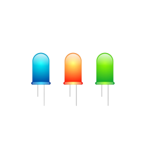


For the irradiation end of the fast PCR instrument, if a Through hole Round LED with a diameter of 5/8/10mm is used, the optimized optical path is shown in Figure
1. The light emitted by the through hole LED first passes through a plano-convex glass lens, then filters the light through a filter, and finally converges the light into the optical fiber through a glass spherical lens. Plano-convex glass lens and filter, glass ball lens through optical fiber, numerical aperture NA = 0.56. Spacing between filter and glass ball lens = 3-5mm. The light spot on the fiber end face is shown in Figure
2. ZEMAX simulation found that the energy utilization rate of light is about 25.658%, compared with SMD LEDs (the energy utilization rate of light is about 85%)
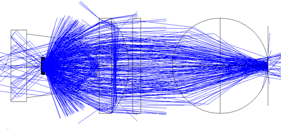
Figure 1 Light path at the irradiated end (using Through hole LED)
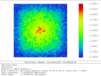
Figure 2 Spot on the fiber end face
The above simulations are based on a wafer of medium to high power chips. Assuming that the thickness of the LED chip is 120 μm, all six sides of the wafer are illuminated. The wafer is in contact with the bottom of the holder’s reflective cup.
The drive current of the Through hole LED is expected to be 100mA. If it is greater than 100mA, the light intensity at the moment of lighting is high. If it is lower than 100mA, the light intensity is not enough to excite the fluorescence of low-concentration reagents, which will affect the sensitivity.
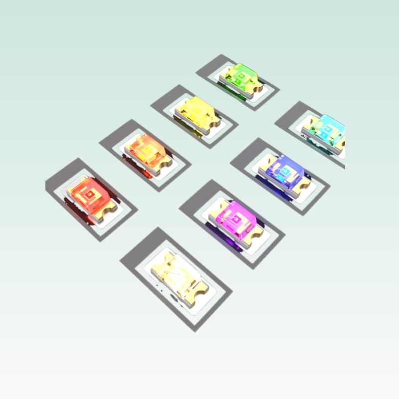
In terms of wavelength selection for through hole LEDs, the following are preferred:
1. Peak wavelength 430nm;
2. Peak wavelength 470nm;
3. Peak wavelength 520nm;
4. Color temperature 4000K full-spectrum white light;
5. Peak wavelength 630nm, or color temperature 3000K
6. The peak wavelength is 740nm.
Explore More from Queendom Lamp
Stay updated with the latest LED technology, lighting solutions, and industry insights.
Request a Quote About Queendom